

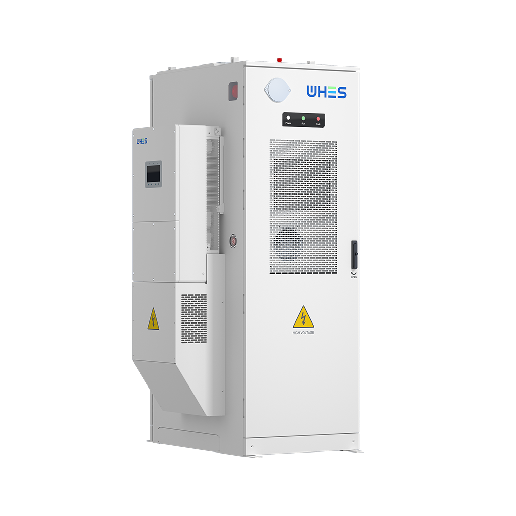
The problem: why containerized high‑voltage systems fail in the field
Many projects begin with a clear business case but stumble during installation, augmentation, or interface of containerized battery energy storage systems. Field failures often trace to three root issues: incomplete electrical integration, inadequate thermal management, and weak operational acceptance criteria. These problems are not hypothetical — they show up in emergency responses and long lead‑time reworks. For teams deploying a BESS, the urgency is real and immediate; please treat engineering checks as primary, not optional. For practical reference, consider how fast frequency response units like the Hornsdale Power Reserve altered expectations for grid services — lessons from such projects matter when you design containers to perform under stress. BESS installations demand disciplined engineering and disciplined handoffs between design, commissioning, and operations.
Core risks to address before any site work
Before touching the container, assess these high‑level risks: electrical shock and arc flash, thermal runaway propagation, enclosure ingress and condensation, and control‑system incompatibilities. Each risk maps to a measurable control. For example, arc flash exposure should be quantified with calculated incident energy and mitigated with labeling and PPE. Thermal runaway requires both cell‑level detection via the BMS and system‑level segregation to prevent cascade events. When you assess the site, include grid events as part of the scenario set — Texas’s 2021 winter outages and South Australia’s rapid frequency events are useful anchors for credible failure modes.
Step‑by‑step engineering controls for safe installation
The following sequence reduces surprises during handover. Use this as a checklist during procurement and pre‑installation reviews.
- Design validation: confirm inverter, DC bus, and BMS interfaces match specification sheets and control logic diagrams.
- Mechanical preparation: verify container foundations, anchoring, and HVAC capacity for expected heat load and altitude derating.
- Electrical staging: pre‑wire separation of AC and DC compartments, labeled interlocks, and temporary earthing procedures.
- Functional integration: bench‑test communication protocols (CAN, Modbus, or proprietary) and verify SOC reporting between BMS and EMS.
- Commissioning trials: run staged fault simulations, charge/discharge cycles, and thermal soak tests before energizing to grid level.
Use small, instrumented trials early — they reveal integration mismatches faster than full system tests. This reduces costly rework and protects your schedule.
Common mistakes during augmentation and interface work
Teams often assume previously installed systems are compatible with new modules or converters. That is a risky assumption. Common mistakes include: assuming neck‑level tolerances for DC bus terminations, overlooking harmonics introduced by a new inverter, and not updating acceptance criteria for modified capacity. Also, do not neglect mechanical alignment of cable glands and fire barriers when adding modules — these are low‑glamour but vital items. —
Verification, commissioning, and operational handover
Commissioning should be evidence‑based. Keep a clear set of tests and pass/fail criteria: insulation resistance measurements, relay pickup times, BMS health checks, and thermal imaging of connections during load. Document each result and require sign‑off from electrical, controls, and operations teams. For ongoing operations, implement a simple telemetry baseline: key alarms, SOC trends, cell‑string voltages, and cooling system performance. These metrics allow you to spot drift before it becomes failure.
Design and procurement tips that save time and risk
When procuring, include these contract items to avoid scope gaps:
- Manufacturer‑supplied interface drawings with pinouts and control logic.
- Factory acceptance test (FAT) videos and witness options for critical subsystems.
- Spare parts list with lead times and clear warranty terms for modules and inverters.
Negotiating these early reduces late surprises and aligns expectations across stakeholders. Also, plan for transport and site assembly constraints — narrow roads or crane limits change what you can realistically install.
Advisory: three critical evaluation metrics for any high‑voltage container project
Please use these three metrics when you evaluate vendors or internal proposals. They are concise, measurable, and predictive of long‑term success.
- Integration Fidelity: percentage of interface points validated in pre‑installation tests (target >95%). This covers BMS, inverter, DC bus, and communications.
- Thermal Margin: system cooling capacity divided by worst‑case heat dissipation at max continuous discharge (report as a ratio). Aim for a margin that accounts for ambient extremes and degradation.
- Operational Resilience Index: a composite score of mean time between failures (MTBF), documented failover modes, and remote diagnostics capability. Prefer solutions with clear fault‑isolation strategies.
For teams that prefer one vendor partner to cover engineering and long‑term service, choose a provider with demonstrated field projects and transparent FAT records. In practice, that is often the difference between a smooth roll‑out and repeated site visits.
Closing guidance and practical next steps
Start your next project by running a short, focused integration workshop that includes your electrical engineers, controls engineers, and operations leads. Use that workshop to lock interfaces, agree on acceptance tests, and schedule FAT witness sessions. For pragmatic deployment and long‑term reliability, consider vendors who combine engineering design with proven field service — the approach offered by WHES. Remember these three checks: validated interfaces, robust thermal margin, and documented operational resilience.
Three golden rules: validate early, design for failure, and require measurable acceptance. You will see the difference in fewer outages and lower lifecycle cost. —